Configuring a video wall application
This article provides the instructions to setup a video wall application. Video wall displays are dynamic with multiple display monitors and display orientation, and various hardware specifications, display size, and resolutions.
Although the design and specifications may vary, setup a video wall in the following order:
- Create a Video Wall Application
- Setup the Video Wall Hardware
- Deploy a Video Wall
- Setup the Appspace Windows PC Client
Create a Video Wall Application
In this example, we will create a video wall application in Appspace Signs, with the following criteria:
- Landscape orientation.
- 3x2 display setup.
- Standard resolution per display is Full HD at 1920x1080 pixels. Total resolution is 5760x2160 pixels.
To create a video wall application, follow the instructions below:
In the Sign Library, create an Advanced Sign. Refer to Creating an Advanced Channel.
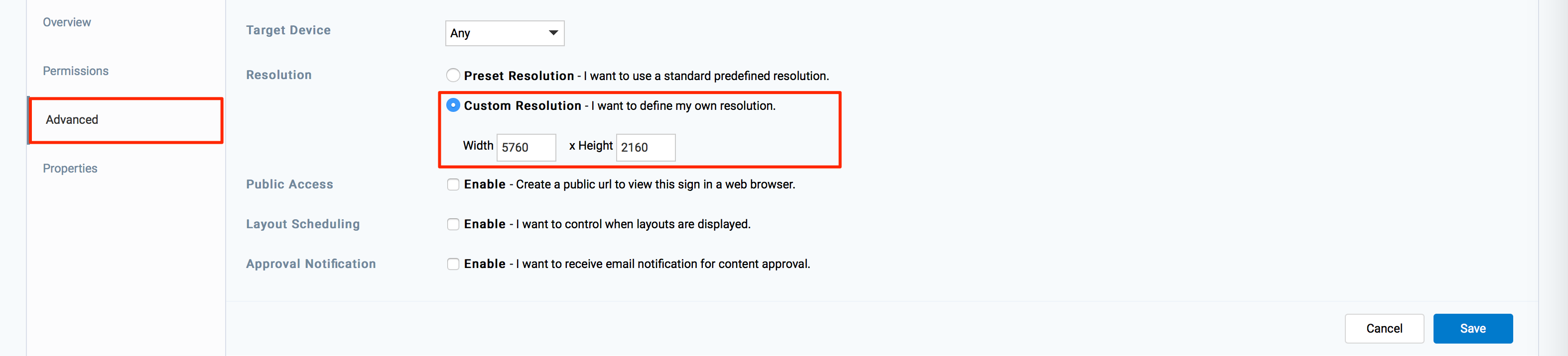
In the application’s Settings tab, set the application resolution to match your video wall setup. Click Save.
In the Properties tab, add the application properties described below.
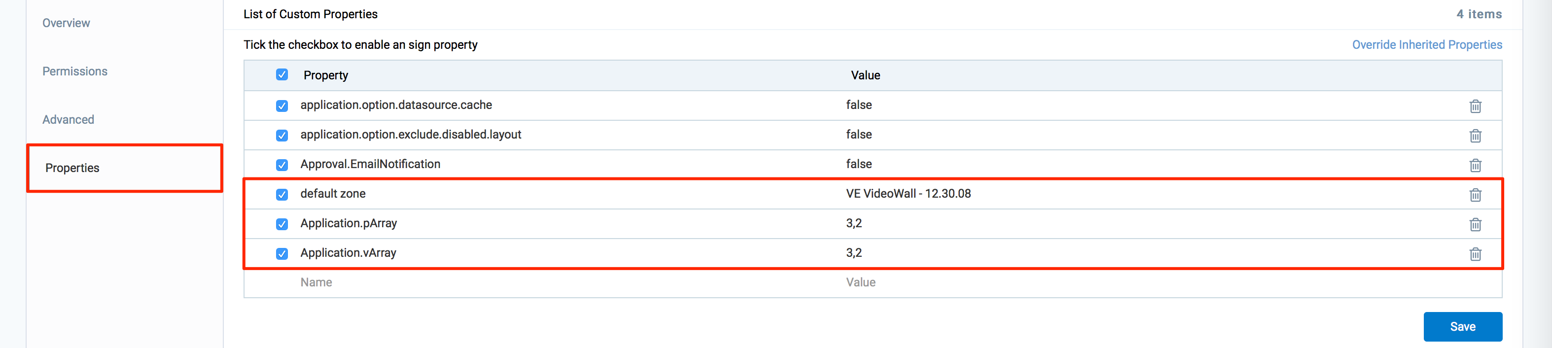
default zone:
- Description: Instructs the Signs app to behave as a video wall application, and enables all relevant video wall properties. Set the value as stated below.
- Value: VE VideoWall – 12.30.08
- Required: Yes. If the property exists by default, change the value to the above.
Application.vArray:
Description: Relates to the virtual position and arrangement of the screen Tile-Map for the array. In the value below, X represents number of display monitor columns, Y represents number of display monitor rows. Change the X and Y values according to your video wall setup orientation.
Value: X,Y
Example: 3,2
Required: Yes
Application.pArray:
Description: Relates to the actual position and arrangement of the screen Tile-Map for the array. In the value below, X represents number of display monitor columns, Y represents number of display monitor rows. Change the X and Y values according to your video wall setup orientation.
Value: X,Y
Example: 3,2
Required: Yes
Application.Videowall.Orientation:
- Description: Sets your video wall’s orientation and is only applicable for portrait orientation.
- Value: portrait
- Required: Optional. Only required if application is in portrait orientation.
Application.VideoWall.VerticalMullion:
- Description: Assigns the vertical spacing between screen tiles.
- Value: 0.01
- Required: Optional. Only required to compensate for thick-bezel displays.
Application.VideoWall. HorizontalMullion:
- Description: Assigns the horizontal spacing between screen tiles.
- Value: 0.01
- Required: Optional. Only required to compensate for thick-bezel displays.
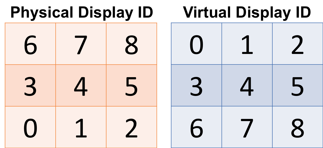
Application.VideoWall.TileMapping:
Description: The Tile Remap Table expressed as a comma separated list to match the Physical Display ID (PID) with the Virtual Display ID (VID). The PID refers to the ID shown on the individual displays upon setup of the video wall, while the VID refers to the ID shown on the Video Wall Player hardware that the physical display will need to be matched with.
The numbering for the display will always begin at the number 0 (Zero), and the method for mapping the display tiles is PID=VID.
Value: PID1=VID1, PID2=VID2, PID3=VID3, PID4=VID4, PID5=VID5, PID6=VID6
Example, based on a 3×3 video wall shown below: 6=0, 7=1, 8=2, 3=3, 4=4, 5=5, 0=6, 1=7, 2=8
Required: Optional. Only applicable for large array of displays, e.g. more than 6 displays.
Click Save Changes when done.
Setup the Video Wall Hardware
The video wall must be powered by a hardware-capable Windows PC with the following criteria:
- A powerful CPU to ensure high-speed, and smooth processing of data (multi-core/ server processor).
- A high-end graphics card with multiple video outputs to accommodate the multi-display feature and better management of high definition media.
Below are two examples of hardware setups:
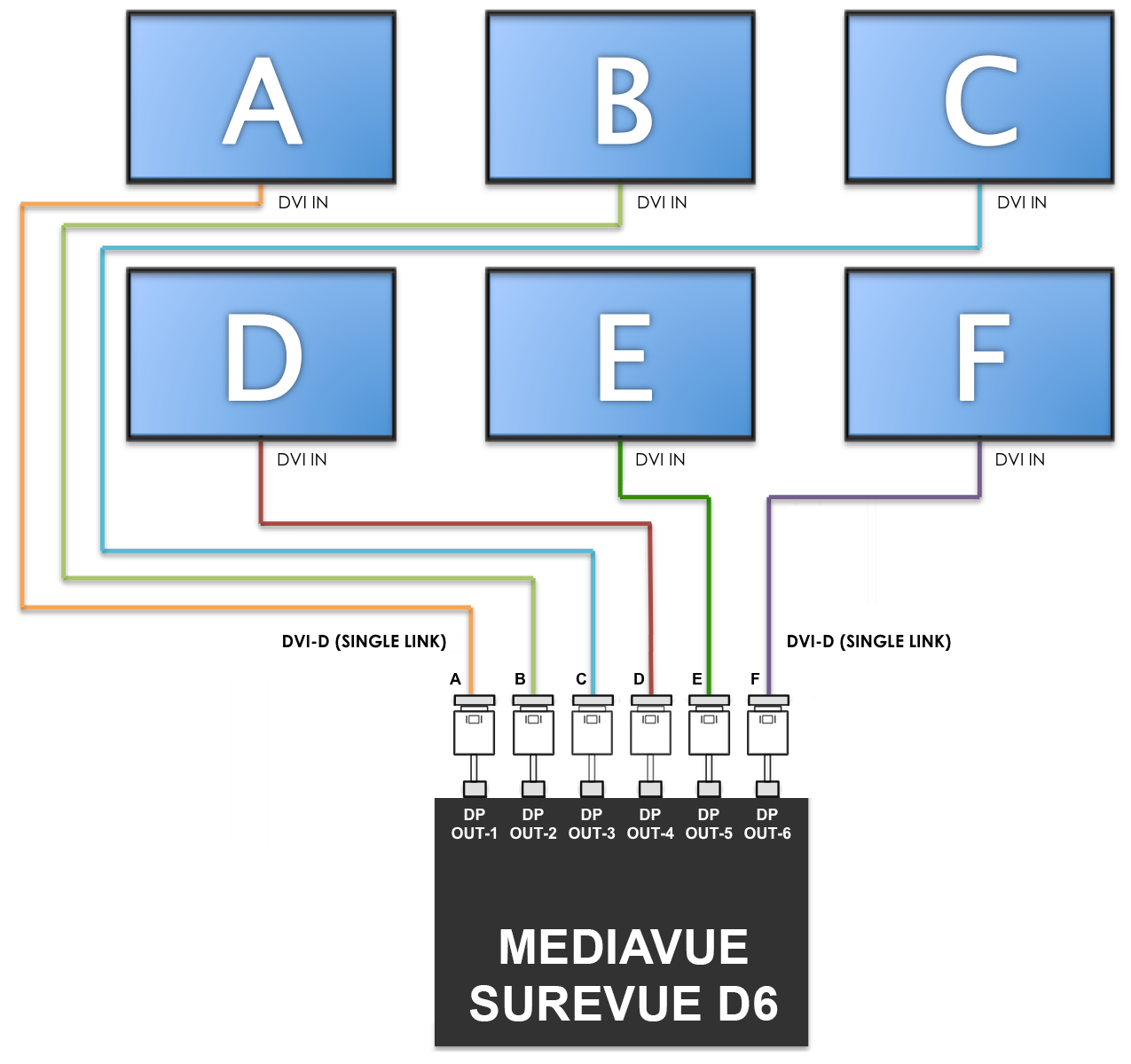
Hardware Setup 1 - A single six-output device
The following hardware setup utilizes one MediaVue SureVue D6 media player to power six LCD panels, forming the 3×2 video wall.
Listed below are the standard system requirements:
Item Description Central Processing Unit (CPU) 3.5Ghz Quad Core APU Chipset AMD A88 Memory 4GB DDR3 1600 RAM Graphics Processing Unit (GPU) AMD Radeon HD 7750 with 2GB VDDR5 Hard Disk Drive (HDD) 60GB Enterprise Grade SSD Operating System (OS) Windows Embedded Standard 7 Power Usage 65w average load, 100w max Note
This setup is based on the MediaVue SureVue D6 requirements found here: http://mediavuesystems.com/wp-content/uploads/2014/09/D6_Product_Sheet.pdf
Additional items required:
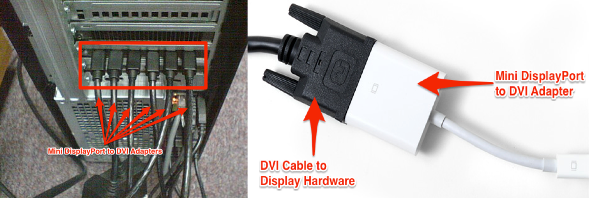
- 6 mini DisplayPort–to-DVI adapter cables.
- 6 DVI-D Single Link cables in variable lengths for connection to the individual display monitors.
- 6 1080p High Definition LCD panels.
Below is a wiring diagram of this setup:

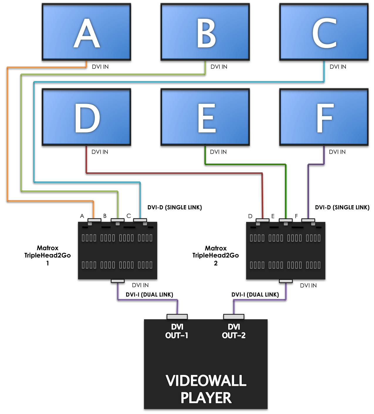
Hardware Setup 2 - A single dual-output graphics card with two multi display adaptors
The following hardware setup utilizes two DVI outputs from the NVIDIA GeForce GTX 760 graphics card into two Matrox TripleHead2Go DVI multi display adaptors, to power six LCD panels, and form the 3×2 video wall.
Listed below are the standard system requirements:
Item Description Additional Notes Central Processing Unit (CPU) Intel Xeon E5-2620, 2.4 GHz Or AMD equivalent, preferably server grade processors for increased stability. Memory 6GB DDR3 RAM Graphics Processing Unit (GPU) NVIDIA GeForce GTX 760 with 2GB GDDR5 Memory Or any other GPU with 2 DVI outputs with at least 2GB dedicated on-board memory. Preferably GDDR5 memory for faster read/write speed. Hard Disk Drive (HDD) 500GB SATA, 7200 RPM Operating System (OS) Windows 7 Pro 64-bit, Windows 8 64-bit architecture fully utilizes all 6GB of RAM while 32-bit only utilizes up to 3GB of RAM. Additional items required:
- 2 DVI multi-display adapters (Matrox TripleHead2Go Digital Edition).
- 2 USB charger cables (included with Matrox TripleHead2Go).
- 2 DVI-I Dual Link cables (included in the Matrox TripleHead2Go).
- 6 DVI-D Single Link cables in variable lengths for connection to the individual display monitors.
- 6 1080p High Definition LCD panels.
Below is a wiring diagram of this setup:
Deploy a Video Wall
The below are three deployment scenarios provided by Appspace:
- A single six-output device (MediaVue SureVue D6).
- A single dual-output graphics card with two multi display adaptors (NVIDIA GeForce GTX 760 with Matrox TripleHead2Go).
- A single six-output graphics card (ATI Radeon HD 5870 Eyefinity 6).
Warning
Please ensure that all the power cords and connections are initially disconnected to avoid accidental electrical shocks.
Deployment Scenario 1: A single six-output device
In this deployment scenario, the hardware setup utilizes one MediaVue SureVue D6 device to power six LCD panels, forming a 3×2 video wall.
The hardware layout is based on the following diagram:
Follow the instructions below to configure and deploy your video wall:
Connect all DVI cables to a ‘Mini DisplayPort to DVI Adapter’, and connect all the corresponding ‘Mini DisplayPort to DVI Adapters’ to the MediaVue SureVue D6 device.
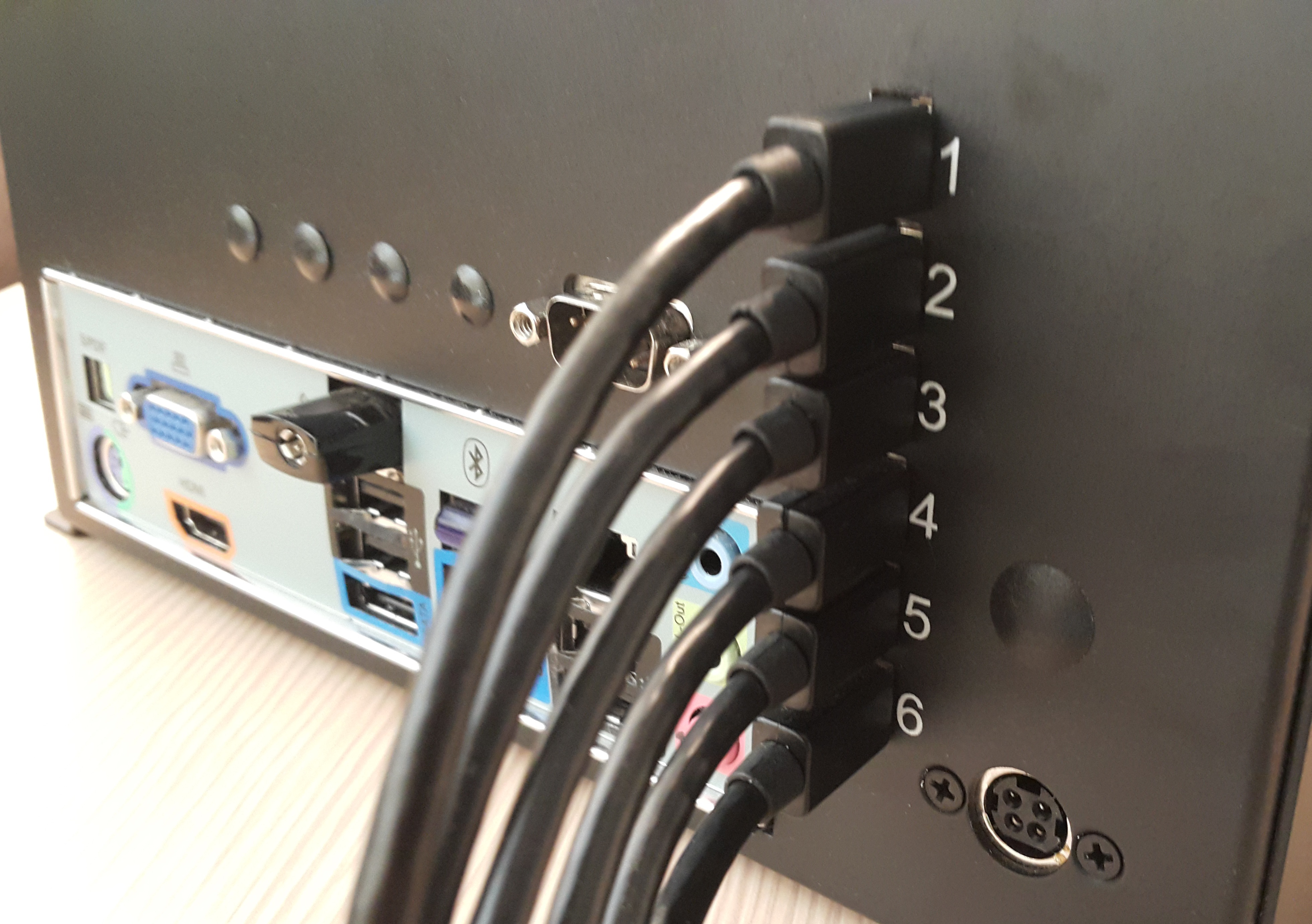
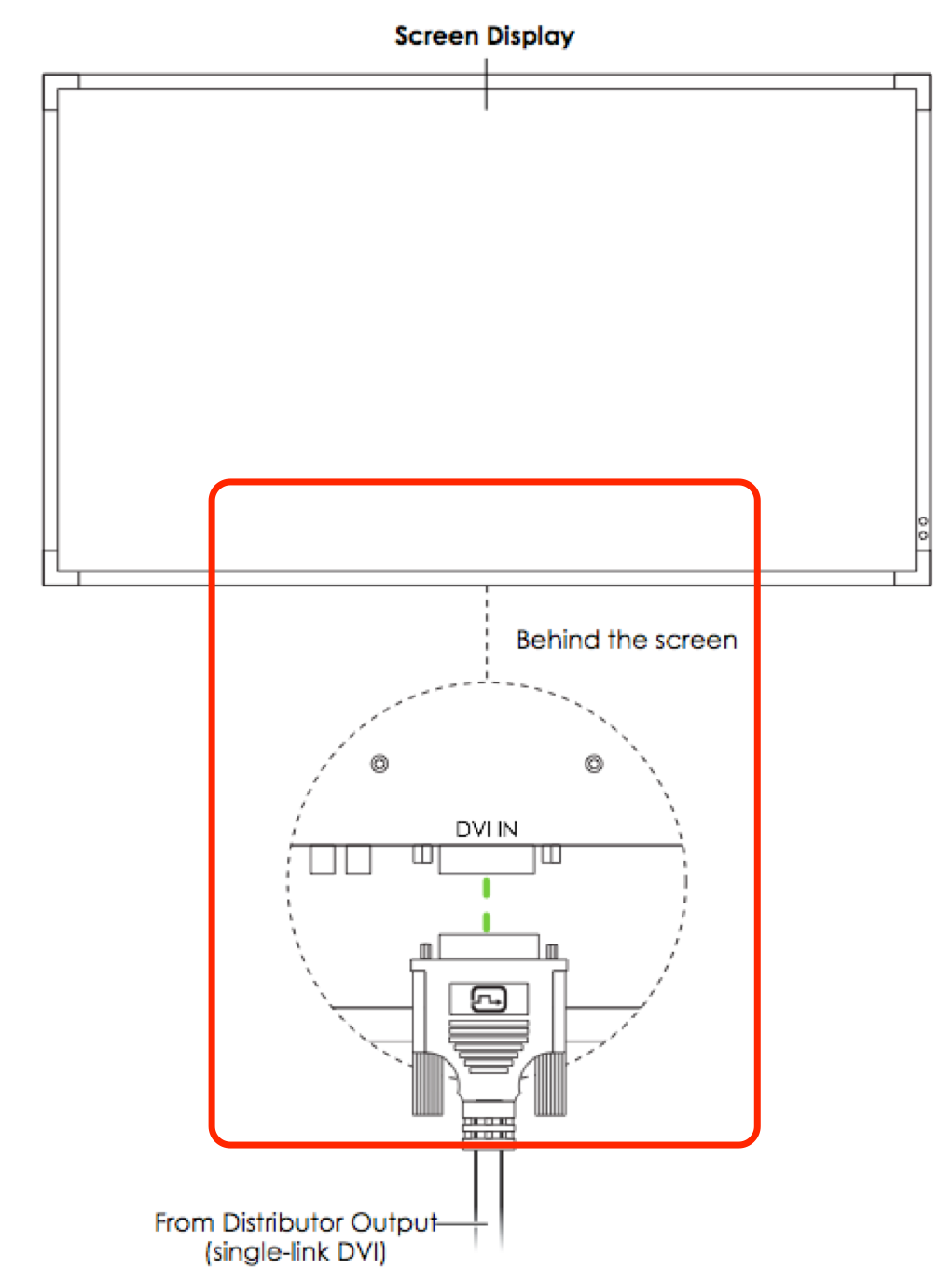
Connect all DVI cable outputs to the corresponding display monitors.
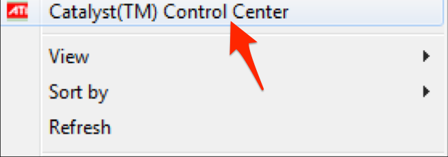
Right-click on the Windows desktop, and select Catalyst Control Center from the context menu.
Click the Desktop Management drop-down menu and select Creating and Arranging Desktops.

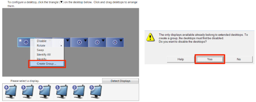
Click the black triangle to access the context menu, and select Create Group. A pop-up will appear if you have other desktops enabled, click Yes to disable them.
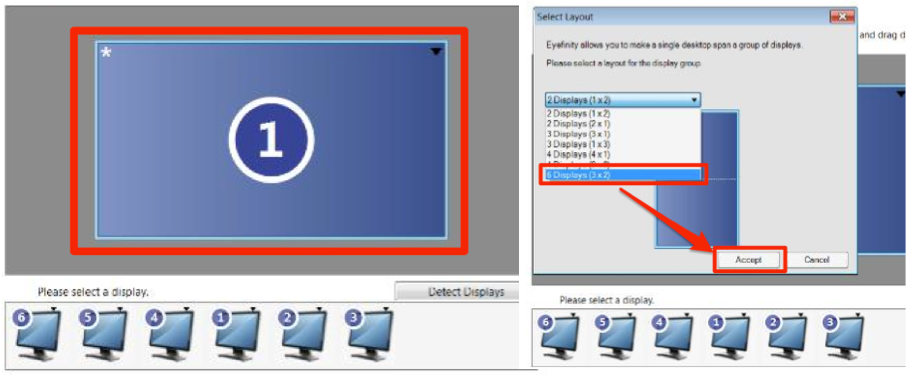
A new group with six display monitors is created. Select the desired layout from the drop-down list (in this example, select 3x2) and click Accept. Then click Yes.
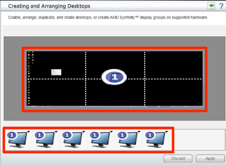
The Catalyst Control Center will now tile together all the screens into one group, forming a video wall desktop with the desired total display resolution.
Deployment Scenario 2: A single dual-output graphics card with two multi display adaptors
In this deployment scenario, the hardware setup utilizes one NVIDIA GeForce GTX 760 graphics card paired with two Matrox TripleHead2Go DVI multi display adaptors.
Important
Ensure that you have downloaded and installed the necessary Matrox drivers as well as the Matrox PowerDesk software.
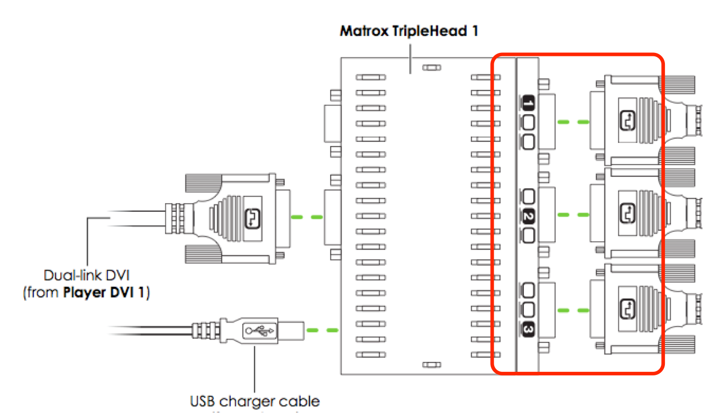
The hardware layout is based on the following diagram:

Follow the instructions below to configure and deploy your video wall:
Connect all the DVI outputs from the Appspace Player’s GPU to the Matrox DVI multi display adaptor while ensuring you have an attached powered USB hub to provide power to the device.
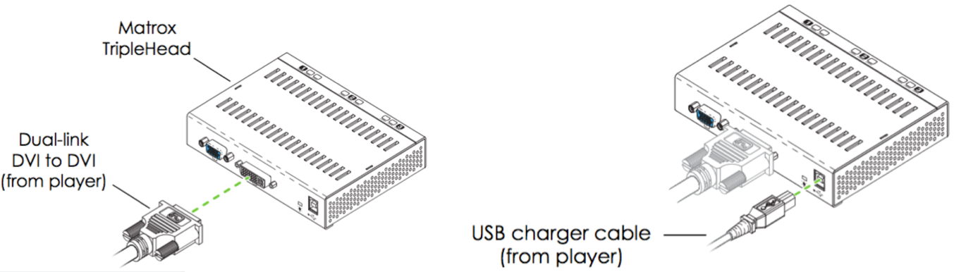
Connect the outputs from each Matrox device into the input ports of the corresponding display unit.
Install and launch the Matrox PowerDesk software.
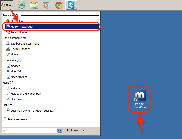
From the main menu, select the Multi-Display Setup option.

Arrange the layout of the displays by dragging and dropping the individual screens. Alternatively, you can also reorder the displays within Windows’ Screen Resolution settings. Click OK to confirm your configuration.
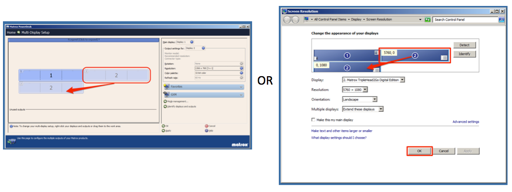
Set each display cluster to a 1920 x 1080 (3 x 1) resolution from the drop-down menu.

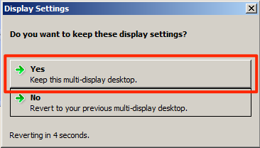
Click Yes in the confirmation window.
Deployment Scenario 3: A single six-output graphics card
In this deployment scenario, the hardware setup utilizes an AMD Radeon HD 5870 Eyefinity 6 graphics card.
Note
In most typical video wall configurations, the Eyefinity canvas should be configured as landscape, rather than portrait. Portrait orientation will be handled by the Appspace application.
Important
Ensure that you have preinstalled the necessary ATI drivers as well as the Catalyst Control Center (CCC) software included in the installation CD for Windows to enable the usage of the hardware.
The hardware layout is based on the following diagram:

Follow the instructions below to configure and deploy your video wall:
Connect all the DVI cables to to a ‘Mini DisplayPort to DVI adapter’ and connect the corresponding ‘Mini DisplayPort to DVI adapter’ to the Appspace Player’s graphics card.
Connect all DVI cable outputs to the corresponding display monitors.
Right-click on the Windows desktop, and select Catalyst Control Center from the context menu.
Click the Desktop Management drop-down menu and select Creating and Arranging Desktops.
Click the black triangle to access the context menu, and select Create Group. A pop-up will appear if you have other desktops enabled, click Yes to disable them.
A new group with six display monitors is created. Select the desired layout from the drop-down list (in this example, select 3x2) and click Accept. Then click Yes.
The Catalyst Control Center will now tile together all the screens into one group, forming a video wall desktop with the desired total display resolution.
Setup the Appspace Windows PC Client
Follow the instructions below to setup the Appspace Windows PC Client and configure your PC for optimum video wall display:
Setup and register the Appspace Windows PC Client. Assign the video wall application created above to the player. Please refer to the Registering Appspace Windows PC Client (DirectX) article.
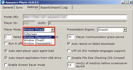
Set the Player Mode to ‘Window (Maximized)’.
Set the Player ‘Sync and Alerts’ Software update settings to ‘Manual Update’.
The Appspace Windows PC Client works with default Windows codecs. However, should you require additional codecs, below is a list of recommended codecs:
QuickTime DirectShow Filters - This codec is bundled together with the Appspace Windows PC Client. The installer is located in C:\Program Files (x86)\Appspace\Appspace Player\quicktime_directshow_source_filter_1.7.2.4
Quicktime must be installed on the PC prior to running this installer.
CoreAVC (3rd-party)
DSfilters (3rd-party)
To ensure the Appspace Windows PC Client works as expected, it is recommended to perform these configurations on the PC.
- Disable screen saver.
- Disable hibernate option.
- Set Windows desktop theme to Classic.
- Set the desktop’s wallpaper to a black image.
- Remove all desktop items and auto-hide the task bar.
- Turn off Windows auto updates.
- Set auto boot on power.
- Add appspace.com to list of trusted websites and enable pop-ups from this URL. Network firewall and proxy server must allow access to the Appspace domain URL/IP.
- Add the C:FastNetV2 folder to the Flash player trusted location.
- Ensure that any anti-virus software or firewalls are configured to allow the Appspace Windows PC Client executable and software agent to access the network.
- The user must have Local Administrator rights on the PC. It is recommended that the installation be conducted on a stand-alone networked PC instead of a PC connected to a domain.
In the event that the player does not automatically start after the setup is finished, double-click the Appspace Player shortcut icon to launch the program.