Creating a Video Wall Application
Introduction
Due to the dynamic nature of Video Walls, there is a wide array of variables to consider when creating a video wall application (E.g. size/arrangement of displays, hardware specifications, display orientation). As such, there are no hard and fast rules for deploying a video wall solution. However, these are the four basic tasks that must be followed in order to ensure all the bases are covered:
- Creating a Video Wall Application
- Preparing the Video Wall Hardware
- Preparing the Video Wall Software
- Deploying the Video Wall
This article serves as a basic guide for the first task, by illustrating the steps to create a simple video wall application specific to a standard 3×2, 12 Megapixel (5760×2160 pixels) video wall in landscape orientation.
Note
Ensure that the prerequisites for installing and licensing the Video Wall extension is met prior to creating this type of application.
Creating a Video Wall Application
In this example, we will be creating a landscape-oriented video wall application based on a 3 by 2 display setup (3 monitors across, 2 rows down).
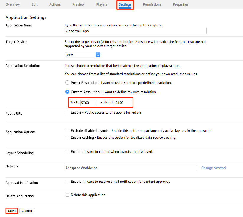
The standard resolution per a display is Full HD at 1920×1080 pixels, thus for a 3×2 display setup, the total resolution we will be setting is 5760×2160 pixels.
Step 1
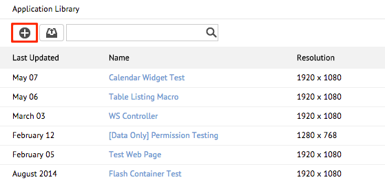
From the Application Library, click the add button to create a new application.
Step 2
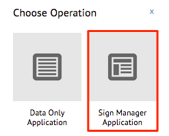
Select Sign Manager Application and create your video wall application from a blank template.
Step 3
From the settings tab, set your application resolution to match your video wall setup. Click Save.
Step 4
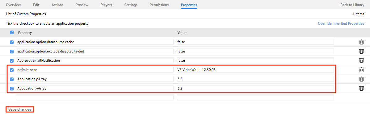
Under the Properties tab, add the properties shown below and click Save Changes when done. Note that you may have to replace the app’s default zone value.
Note
The application properties that we use for this example are:
- default zone: VE VideoWall – 12.30.08
- Application.pArray: 3,2
- Application.vArray: 3,2
Video Wall Application Player Properties
The following list describes the purpose of each player property that is configured in the Properties tab of the video wall application, as well as the sample value it may contain.
default zone
- Description – The property that tells the app to behave as a video wall application, and enables all relevant video wall properties
- Value – VE VideoWall – 12.30.08 (mandatory)
- Required – Yes
Application.vArray
- Description – Relates to the virtual position and arrangement of the screen Tile-Map for the array
- Value – 3×2 video wall, therefore 3,2
- Required – Yes
Application.pArray
- Description – Relates to the actual position and arrangement of the screen Tile-Map for the array
- Value – 3×2 video wall, therefore 3,2
- Required – Yes
Application.Videowall.Orientation
- Description – Sets your video wall’s orientation (only applies for portrait application)
- Value – portrait
- Required – No (portrait video walls only)
Application.VideoWall.VerticalMullion
- Description – Assigns the vertical spacing between screen tiles (optional)
- Value – 0.01
- Required – No (only required to compensate for thick-bezel displays)
Application.VideoWall. HorizontalMullion
- Description – Assigns the horizontal spacing between screen tiles (optional)
- Value – 0.01
- Required – No (only required to compensate for thick-bezel displays)
Application.VideoWall.TileMapping
- Description – The Tile Remap Table expressed as a comma separated list, to match the Physical Display ID (PD ID) with the Virtual Display ID (VD ID) (Note: only applies for large array of displays, e.g. beyond 6 screens)
- Value – 6=0, 7=1, 8=2, 3=3, 4=4, 5=5, 6=6, 0=6, 1=7, 2=8 (Based on an example of a 3×3 video wall)
- Required – No (only for larger video walls)
Physical Display ID and Virtual Display ID Diagram
This diagram is an example of a 3×3 video wall setup where the physical display and its virtual reference do not match and will need configuration to ensure proper placement of the content.
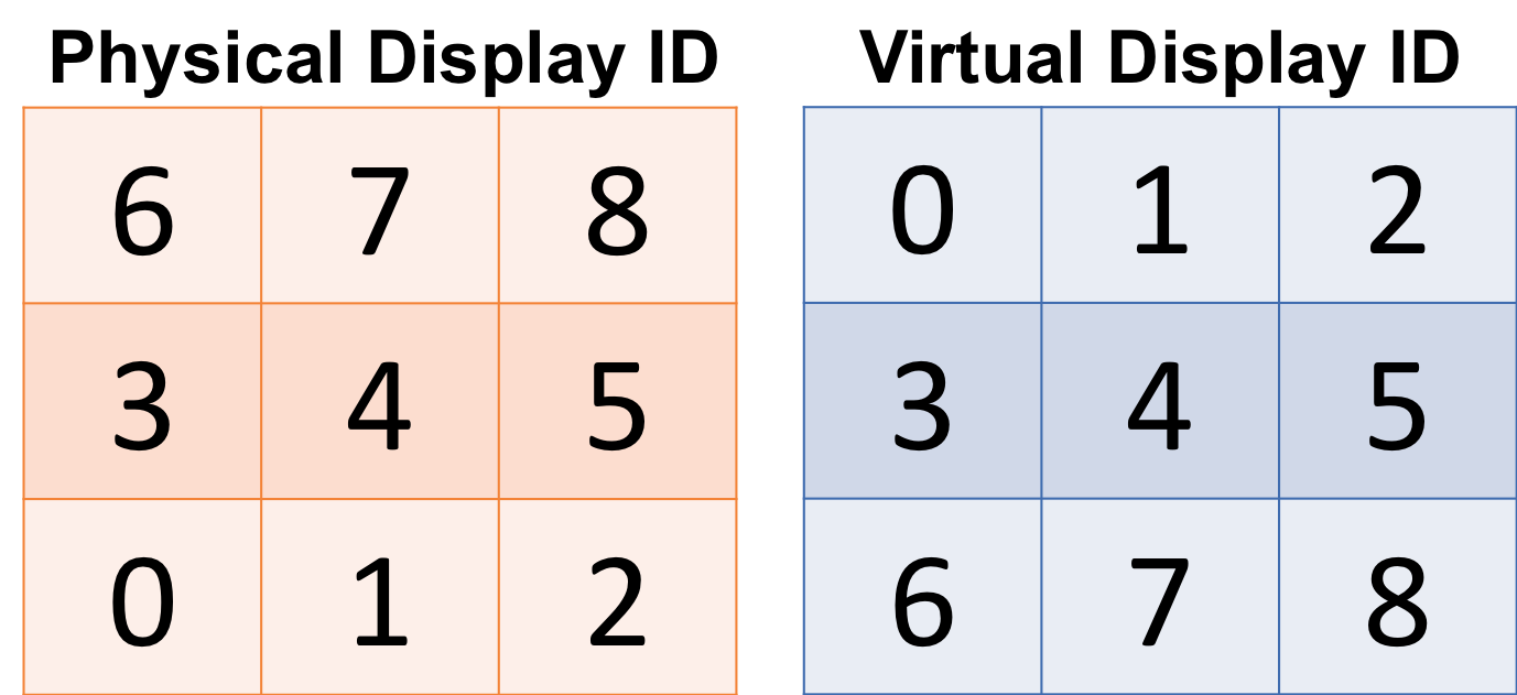
The Physical Display ID refers to the ID shown on the individual displays upon setup of the video wall, while the Virtual Display ID refers to the ID shown on the Video Wall Player hardware that the physical display will need to be matched up with.
The numbering for the display will always begin at the number 0 (Zero), and the method for mapping the display tiles is Physical ID (PID)=Virtual ID (VID).
From this example, the first tile for the PID is 6, and the corresponding tile in the VID is 0, so the pairing will be 6=0. The next pair will be 7=1, and so on.
(The final setting, based on the example above will be: 6=0,7=1,8=2,3=3,4=4,5=5,6=6,0=6,1=7,2=8)